Automatic Damper Wiring Diagram
This video is part of the heating and cooling series o. This one covers how to wire the fresh air damper for a furnace without the air conditioner coming on.
 Ty 2160 Automatic Damper Wiring Diagram Download Diagram
D Automatic Vent Damper APPLICATION The D Automatic Vent Damper is a 24 Vac motorized stack damper.
Automatic damper wiring diagram. Wiring is the same for AOBD AOBD-BM and IOBD Dampers. Honeywell automatic vent damper emergency bypass hi the device is a honeywell d80 installed in 1994. While not frequent th.
D896 automatic vent dampers are used with atmospheric visual indicator shows damper position. It shows the parts of the circuit as simplified forms as well as the power and signal links between the gadgets. WIRING A DAMPER TO A 5 CONTROL PANEL.
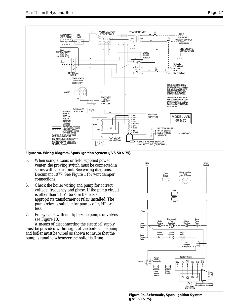
12 4 5 3 6 X Z M6 M5 M4 M2 M1 CLOSED OPEN 24 VOLTS NOTE. AOBD Damper wiring multiple. Damper Q35 M35 Actuator M35 Y84 Wiring Cover Harness Q15 Ignition System Figure 1.
ADA-1 Automatic Damper Adapter Instruction Manual Wiring Diagram. Field Controls GVD gas vent damper was developed to reduce off cycle venting 5. A wiring diagram is a streamlined conventional pictorial depiction of an electric circuit.
Gvd-6 Wiring Diagram Field Controls GVD-6PL - 6 Automatic GVD Vent Damper without harness - Note. Installation mounting operation instructions plus wiring instructions for the ADA-1 Automatic Damper Adapter. Field Controls GVD Field Controls GVD-6PL - 6 Automatic GVD Vent Damper without harness - Note.
ARD or ZD Damper wiring diagram. Q35 MIZER Automatic Vent Damper System and Q15 Ignition System The Q35 energy-saving high-efficiency automatic vent damper system retains heat that is normally wasted through the open flue when the appliance is not firing. This Keyed wiring harness connector plug installs only one way preventing.
A wiring diagram is a streamlined conventional pictorial depiction of an electric circuit. It shows the components of the circuit as streamlined shapes and also the power as well as signal connections in between the gadgets. Variety of automatic vent damper wiring diagram.
A wiring diagram is a streamlined conventional photographic depiction of an electrical circuit. It reveals the components of the circuit as simplified shapes as well as the power as well as signal links between the tools. Use the D896 only on.
Control installation EG thru and PEG thru steam boilers with Mount and wire controls per wiring diagram page. It shows the components of the circuit as simplified shapes and the capability and signal contacts between the devices. Use the D only on Wiring diagram for D connection to.
Literally a circuit is the course that enables electrical energy to circulation. The damper closes off the furnace or boiler stack during the heating off-cycle. A wiring diagram is a streamlined standard photographic depiction of an electric circuit.
If your appliance wont fire check of the automatic vent damper. When using a Slave motor wire slave motor as shown in diagram on left. Automatic Vent Damper Wiring Diagram wiring diagram is a simplified suitable pictorial representation of an electrical circuit.
Receiving from point A to point B. Premium Color Wiring Diagrams Get premium wiring diagrams that are available for your vehicle that are accessible Online right now Purchase Full Set of complete wiring diagrams so you can have full Online access to everything you need including premium wiring diagrams fuse and component locations repair information factory recall information and even TSBs Technical Service Bulletins. 24 VAC for simple and low-cost wiring.
For three or more AOBD dampers on one zone a Slave Damper Control Relay SDCR is required. Automatic Vent Damper APPLICATION The D896 Automatic Vent Damper is a 24 Vac motorized stack damper. The damper closes off the furnace or boiler stack during the heating off-cycle.
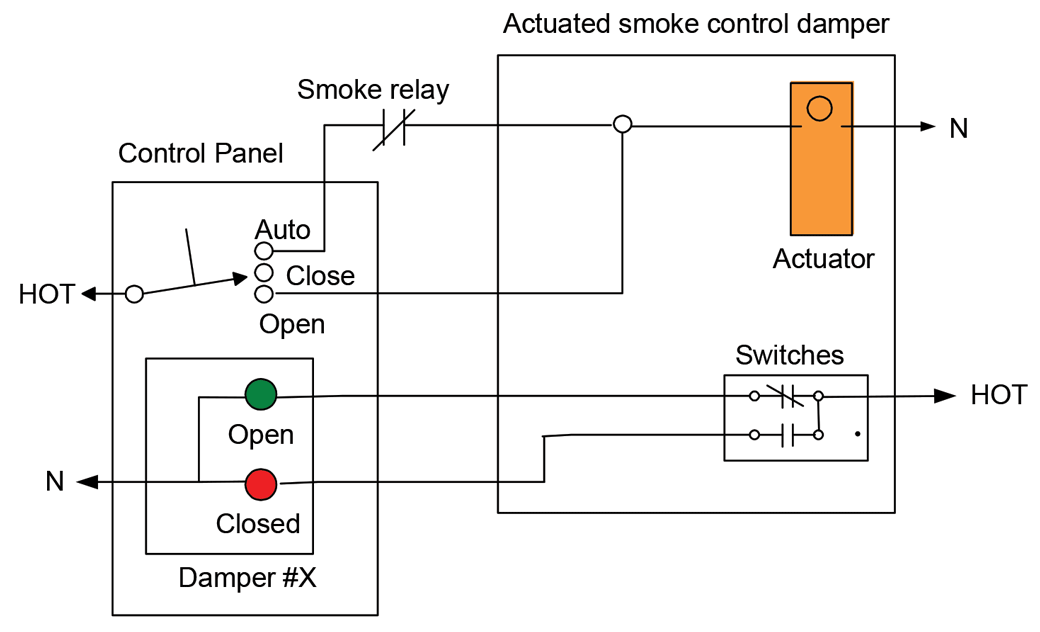
Variety of fire smoke damper wiring diagram. This Keyed wiring harness connector plug installs only one way preventing. WIRING A DAMPER TO A 3 WIRE THERMOSTAT AND SHOWN WITH AN OPTIONAL SLAVE DAMPER.
Collection of fire smoke damper wiring diagram. A wiring diagram usually gives guidance approximately the relative position and covenant of devices and terminals on the devices to help in building or. On a gas fired boiler like a Burnham or Weil Mclain to name a couple the auto vent damper is the first sign of life on a call for heat.
Read Or Download The Diagram Pictures Damper For FREE Wiring Diagram at ETLDATASTRATCOMBR. Wiring diagram for D896 connection to S8600 S8610 using wiring harness with two molex plugs. Multiple dampers can be wired in parallel with up to five dampers wired to each panel.
Automatic vent damper wiring diagram A Novice s Overview of Circuit Diagrams A first take a look at a circuit diagram may be confusing yet if you can read a metro map you can review schematics. MOTOR TERMINALS ON MASTERTROL MARK IV V VII VIII X XXX AND XXXI. Damper Motor Wiring Diagram wiring diagram is a simplified adequate pictorial representation of an electrical circuitIt shows the components of the circuit as simplified shapes and the capacity and signal friends amid the devices.
The Q35 consists of a Y15 damper M35.
 Automatic Flue Damper Not Operating Automatically Doityourself Com Community Forums
 Bb 5901 Air Damper Wiring Diagram Wiring Diagram
 Automatic Vent Damper Wiring Diagram Wiring Site Resource
 Remote Fire And Smoke Damper Testing Nears Hpac Engineering